- The hullform design starts with lines modelled in Rhino3d with the aid of Orca3d where the main particulars and geometry parameters are chosen in order to meet the displacement requirements, deck area and shape constraints, construction limitations (i.e minimum radii, welding angles etc.), while minimizing the estimated resistance. The initial estimation is done through systematic series.
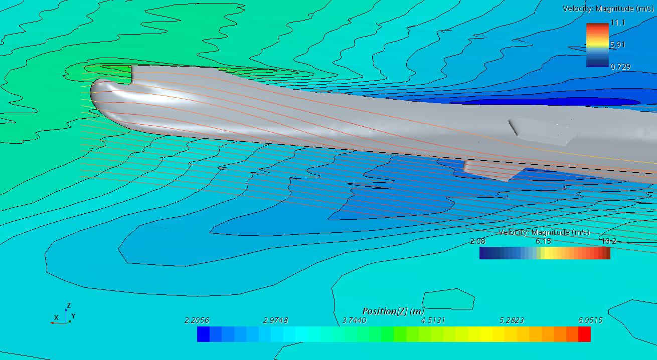
- Additional features in bulb shape, stern transition and propeller tunnels (if needed) are added using internal Tools of Rhino 3d and parameterized by main characteristics. (e.g. different bulb width, height, center, camber etc.)
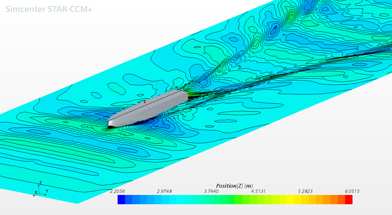
- By systematically varying each parameter, a series of candidate geometries is produced and the resistance of each is calculated, using Viscous CFD (RANSE) solvers like OpenFOAM and StarCCM+ of medium fidelity (i.e. steady simulation, relatively coarser meshes, fixed trim and sinkage), in order to find best candidates.
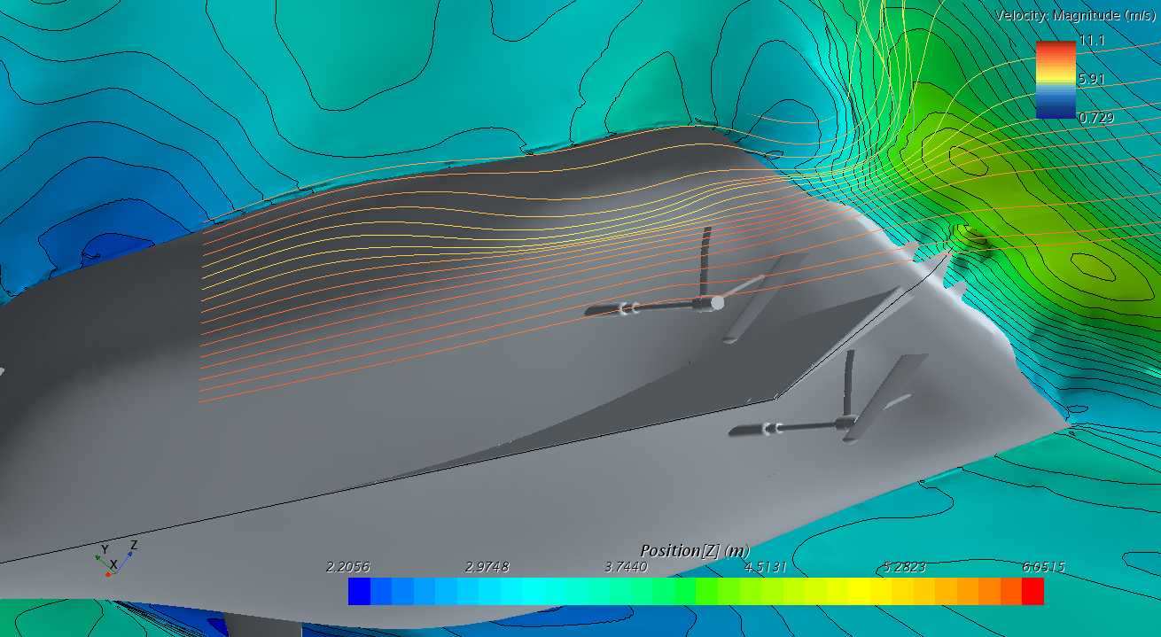
- The best candidates are then simulated using high fidelity CFD (URANS, again OpenFOAM and StarCCM+, but unsteady simulation, fine and very fine meshes, free trim and sinkage) and fine tuned by smaller changes in parameters in order to find the lowest resistance for the operational points needed.
- If the simulations reveal flow features that require further alterations to the geometry, such alterations are performed through smooth deformation tools in Rhino3D and the corresponding events are investigated by simulating at least three candidate geometries of different extent.
- After the top 3 candidates are identified they are also simulated for different conditions, in order to identify the best overall and produce the resistance curve of the final geometry.
- With the resistance curve known and the wakefield extracted from the corresponding simulations, the propeller particulars are selected and optimized using in-house Unsteady BEM tools.
|